Modérateurs: Modération Forum DIY, Modération Forum Installations, Le Bureau de l’Association HCFR • Utilisateurs parcourant ce forum: Aucun utilisateur enregistré et 109 invités

Discussions générales sur le DIY Audio : choix des HP, comparaisons des principes : clos vs BR, etc

Comment induire du délai entre l'allumage de mes appareils ?

Message » 12 Nov 2016 15:17

Bonjour,

J'ai une question, probablement simple, à vous soumettre, je cherche à induire du délai entre chaque allumage de mes amplis.
Je m'explique, dans mon installation, lorsque j'allume mon ampli HC, il y a toute une cascade d'amplis de puissance qui s'allument par le biais de câbles trigger 12v.

L'objectif que je vise est :
- allumage de l'ampli HC
- après 1-2 secondes, allumage du premier ampli de puissance
- après 1-2 secondes, allumage du deuxième ampli de puissance
- etc.
sachant que les triggers sont connectés en chaine, ampli HC -> 1 er ampli -> 2ème ampli -> 3 ème ampli

Donc je me demande si je pourrais intercaler, une sorte de relai retardateur au milieu des mes câbles trigger, qui lorsqu'il recevrait une tension de 12v, attendrait 1-2 secondes avant de la laisser passer pour allumer l'ampli suivant (et qui la laisserait passer tout le temps que les amplis seraient allumés).

Vous avez une idée de ce que je peux utiliser ?

Merci de votre aide :wink:

La configuration dans mon profil


Ne prenez pas la vie trop au sérieux, de toute façon, vous n’en sortirez pas vivant. Bernard le Bovier de Fontenelle
Avatar de l’utilisateur
Jumper
Membre HCFR
Membre HCFR
 
Messages: 3838
Inscription Forum: 13 Oct 2002 20:24
Localisation: Bakistan & Yvelines
  • offline

Message » 12 Nov 2016 16:03

Salut.
En attendant une autre solution, il y a des petits modules à câbler et insérer dans une boîte comme celui-ci
http://m.ebay.com/itm/122041556572

http://s.aliexpress.com/q6rYJNBf
Samsara
 
Messages: 5271
Inscription Forum: 20 Avr 2000 2:00
  • offline

Message » 12 Nov 2016 16:27

Merci, c'est exactement ce type de module que je cherche, j'ai trouvé celui-là :

http://www.ebay.fr/itm/Power-ON-Open-Delay-Timer-relais-Interrupteur-Module-DC-12V-Mieux-que-NE555-/351167067668?hash=item51c3303614:g:Bc8AAOSwfcVUDsaG

qui peut être branché comme cela :

Image

Le schéma du bas à l'air de correspondre à ce que je veux, j'ai bon ?

La configuration dans mon profil


Ne prenez pas la vie trop au sérieux, de toute façon, vous n’en sortirez pas vivant. Bernard le Bovier de Fontenelle
Avatar de l’utilisateur
Jumper
Membre HCFR
Membre HCFR
 
Messages: 3838
Inscription Forum: 13 Oct 2002 20:24
Localisation: Bakistan & Yvelines
  • offline

Message » 12 Nov 2016 16:56

Oui, le fonctionnement est identique pour tout ces modèles.
Autant prendre le moins cher http://www.ebay.fr/itm/NE555-12V-Tempor ... 1093810214 ou https://www.aliexpress.com/item/DC-12V- ... 16994.html

Le problème sera au niveau de la puissance de sortie de tes triggers ,il faut assez d'intensité pour faire coller le relais ,visiblement il faut au moins 37mA sous 12V
https://www.ghielectronics.com/download ... elayX1.pdf
Samsara
 
Messages: 5271
Inscription Forum: 20 Avr 2000 2:00
  • offline

Message » 12 Nov 2016 17:32

Sinon, en pro, tu as ce genre de chose :
https://www.thomann.de/fr/furman_ps_8r_e_iii.htm
mais je ne sais pas si on peut avoir des délais différent pour chaque appareil.
Je suppose que oui.
Sinon, regardé d'autres modèles sur le même site.exemple plus cher : https://www.thomann.de/fr/furman_cn_3600_se.htm
tcli
 
Messages: 4066
Inscription Forum: 23 Nov 2009 22:40
Localisation: Complètement à l'ouest
  • offline

Message » 12 Nov 2016 17:53

c'est l'occasion de se lancer sur un montage à base d'arduino 8) (ou autre pic) ça coutera 5 fois plus cher mais c'est vachement plus amusant et gratifiant :mdr:
maxidcx
Membre HCFR Contributeur
 
Messages: 3103
Inscription Forum: 25 Avr 2007 10:50
  • offline

Message » 12 Nov 2016 18:53

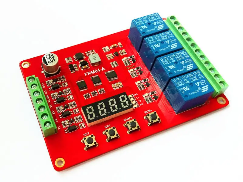
Sinon il y a des modules 4 voies .
Je ne comprend pas bien le fonctionnement de celui-ci qui possède un port série (connecteur 4 pins en bas noté 串口下载程序入口 )
Image
https://www.aliexpress.com/item/Free-sh ... 74462.html

Pour celui-ci le fonctionnement est donné sur la version 2 voies
Image
https://www.aliexpress.com/item/DC-12V- ... 28603.html
Module function:

Users can display the key and select the following 18 kinds of functions in one, you can set and save functionparameters, you can also view the parameters of the current function of the time parameter sets the minimum0.1 seconds adjustable, accuracy better than 0.01 seconds,
Tips: Function 1-8 on power-up self-start function 9-18 require high pulse signal to trigger the start (high duration is shorter than 20ms, hereinafter the same), 9 is a self-locking mode function, function 10 is level control mode.
Function 1:

Timing Pick: After power, time delay relay pull T1, T1 between 0.1 seconds -270 hours adjustable, CH1interface to a high level pulse signal, repeat the above functions;

Function 2:

Timing off: when the power relay, time delay relay disconnected T1, T1 between 0.1 seconds -270 hours adjustable, CH1 interface to a high level pulse signal, repeat the above functions;

Function 3:

Timing pull off again: After power relay to not pull, the delay time T1 reaches the relay is energized; pull the relay off after T2 arrival time, delay time T1 and T2 in 0.1 seconds -270 hours between adjustable to CH1interface a high pulse signal, repeat the above functions;

Function 4:

Timing and then pull off: After power, immediately pull the relay, the relay off delay time T1 after arrival; T2arrive after disconnecting time relay, -270 hour in 0.1 seconds delay time between T1 and T2 adjustable toCH1 interface a high pulse signal, repeat the above functions;

Function 5:

Infinite loop timing mode 1: After power relay to not pull, after the delay time T1 reaches the relay is energized; pull the relay off after time T2 arrives, and then repeat the above condition, the delay time T1 andT2 at 0.1 adjustable between second -270 hours, giving a high level pulse signal CH1 interface, you canrestart the above functions;

Function 6:

Infinite loop timing mode 2: After power, immediately pull the relay delay time T1 reaches the relay off; arriveafter disconnecting time T2 relay, and then repeat the above condition, the delay time T1 and T2 in 0.1 seconds adjustable between -270 hours, giving a high level pulse signal CH1 interface, you can restart the above functions;

Function 7:

Finite loop timing mode 1: After power relay to not pull, the delay time T1 reaches the relay is energized; pulloff the relay arrival time T2, and then repeat the NX times above the state, this time in T1 and T2 adjustablebetween 0.1 seconds -9999 seconds NX cycles adjustable between 1-9999 times, giving a high level pulsesignal CH1 interface, you can restart the above functions;
Function 8:

Finite loop timing mode 2: After power, immediately pull the relay delay time T1 reaches the relay off; arriveafter disconnecting time T2 relay, and then repeat the NX times more state, then T1 and T2 at 0.1 adjustablebetween second -9999 seconds NX cycles adjustable between 1-9999 times, a high-level interface to CH1pulse signal, the above functions can be re-started;

Function 9:

Latching relay modes: CH1 interface to relay a high level pulse signal, relay, give a high pulse signal relaydisconnected.

Function 10:

Trigger relay mode: with delay off function after power relay does not act, a high signal to CH1 interface, the relay immediately pull, the CH1 signal disappears, the relay still pull, pull-time T1 after the arrival relayinterrupted, and the T1 is adjustable between 0 seconds -270 hours.

Note: This feature, if T1 is set to 0 seconds, it becomes: CH1 have high signal relay, no signal is immediatelydisconnected.

Function 11:

Pull the trigger timing: After power relay does not act, a high-level interface to CH1 pulse signal, the delaytime relay pull T1, T1 between 0.1 seconds -270 hours adjustable, repeating a high level interface to CH1pulse signal, repeat the above function;

Function 12:

Trigger timing off: After power relay does not act, a high-level interface to CH1 pulse signal relay, the relay offdelay time T1, T1 between 0.1 seconds -270 hours adjustable, repeat to CH1 interface a high pulse signal,repeat the above functions;

Function 13:

Pull the trigger timing then disconnect: After power relay does not act, CH1 interface to a high level pulsesignal, the delay time T1 reaches the relay is energized; pull the relay off after T2 arrival time, delay time T1and T2 between 0.1 seconds -270 hours adjustable, repeat CH1 interface to a high level pulse signal, repeatthe above functions;

Function 14:

Disconnect and then pull the trigger timing: After power relay does not act, a high-level interface to CH1 pulse signal, immediately pull the relay, the relay off delay time T1 after arrival; T2 arrive after disconnecting timerelay, delay time between T1 and T2 in 0.1 seconds -270 hours adjustable, repeat CH1 interface to a high level pulse signal, repeat the above functions;

Function 15:

Infinite loop timing mode 1: After power relay does not operate to a high level pulse signal CH1 interface, thedelay time T1 reaches the relay is energized; pull off the relay arrival time T2, and then repeat the abovecondition, the extension when the time between T1 and T2 in 0.1 seconds -270 hours adjustable, repeat CH1interface to a high level pulse signal, the above functions can be re-started;

Function 16:

Infinite loop timing mode 2: After power relay does not act, a high-level interface to CH1 pulse signal,immediately pull the relay, the relay off delay time T1 after arrival; break time T2 after reaching relay, thenrepeat the above condition, the delay time between T1 and T2 in 0.1 seconds -270 hours adjustable, repeatCH1 interface to a high level pulse signal, the above functions can be re-started;

Function 17:

Finite loop timing mode 1: After power relay does not act, a high-level interface to CH1 pulse signal, thedelay time T1 reaches the relay is energized; pull the relay off after time T2 arrives, and then repeat the above state NX times , this time between T1 and T2 in 0.1 seconds -9999 seconds adjustable cycles NXadjustable between 1-9999 times, repeating to a high level pulse signal CH1 interface, you can restart the above functions;

Function 18:

Finite loop timing mode 2: After power relay does not act, CH1 interface to a high level pulse signal,immediately pull the relay, the relay off delay time T1 after arrival; break time T2 after reaching relay, thenrepeat NX times above the state, this time between T1 and T2 in 0.1 seconds -9999 seconds adjustablecycles NX adjustable between 1-9999 times, repeating to a high pulse signal CH1 interface, you can startover again function;


Electrical parameters:

Operating voltage: DC 5V, 12V, 24V three options (should not exceed the nominal voltage of + 10%)

Working Current: less than 5V 180mA (when the relay is not operating less than 15mA, turn off the display of less than 3mA)

12V is less than 90mA (when the relay is not operating less than 15mA, turn off the display of less than 3mA)

When 24V is less than 60mA (when the relay is not operating less than 15mA, turn off the display of less than3mA)

Working temperature: Recommended -20 -60 (extreme operating temperature range -30 -70 )

Load capacity: normally open relay ports Maximum load capacity: DC 0-30V / 10A, AC 0-250V / 10A

Relay normally closed port maximum load capacity: DC 0-28V / 10A, AC 0-125V / 10A

Module interface

Module voltage / signal inputs: There are 3-wire interface, all interfaces are terminal, user-friendly

1, DC +: DC power positive

2, DC-: DC power supply negative

3, CH1: an input signal detection interface

4, CH2: Input Signal Detection Interface 2

Load relay outputs: Three line interface, all interfaces have terminal blocks

1, NO1: After the first relay normally open interface and relay before floating, shorted absorbed and COM1

2, COM1: first relay Common Interface

3, NC1: The first way normally closed relay interface and relay COM1 shorted before and after the pull-vacant

4, NO2: after the second relay normally open interface and relay before floating, shorted absorbed andCOM2

5, COM2: second relay Common Interface

6, NC2: second normally closed relay interface and relay before and COM2 short, pull-vacant post

https://www.aliexpress.com/item/DC-12V- ... 48607.html
Samsara
 
Messages: 5271
Inscription Forum: 20 Avr 2000 2:00
  • offline

Message » 31 Déc 2016 16:38

Bon, je remonte mon post.
J'ai acheté et monté le module dont je parlais plus haut :

Image

Connecté à une alimentation 12V, avec mon multimètre en sortie, cela marche parfaitement, j'ai bien le délai programmé avant l'allumage.
Maintenant, connecté à mon pré (McIntosh C1100), dès son allumage, les amplis s'allument tout de suite, sans gérer le délai.
Comme j'en avais acheté 2, j'ai essayé le deuxième, avec le même (dys)fonctionnement.

Vous avez une idée de ce qu'il se passe ?

La configuration dans mon profil


Ne prenez pas la vie trop au sérieux, de toute façon, vous n’en sortirez pas vivant. Bernard le Bovier de Fontenelle
Avatar de l’utilisateur
Jumper
Membre HCFR
Membre HCFR
 
Messages: 3838
Inscription Forum: 13 Oct 2002 20:24
Localisation: Bakistan & Yvelines
  • offline

Message » 31 Déc 2016 17:30

Comment as-tu câblé l'ensemble?
Une fois alimenté ,il suffit d'écouter quand le relais colle ,ce qui indique que la temporisation fonctionne.
D’après la sérigraphie , il suffit de connecter les deux bornes du haut du bornier de gauche : celle du haut est l'entrée 230V (Phase) et celle du milieu va à l'appareil ,le Neutre n'étant pas concerné et va directement à l'appareil.
Samsara
 
Messages: 5271
Inscription Forum: 20 Avr 2000 2:00
  • offline

Message » 31 Déc 2016 18:27

J'ai branché comme sur le schéma du bas :

Image

Et ça marche bien connecté à une alim 12v basique :wtf:

La configuration dans mon profil


Ne prenez pas la vie trop au sérieux, de toute façon, vous n’en sortirez pas vivant. Bernard le Bovier de Fontenelle
Avatar de l’utilisateur
Jumper
Membre HCFR
Membre HCFR
 
Messages: 3838
Inscription Forum: 13 Oct 2002 20:24
Localisation: Bakistan & Yvelines
  • offline

Message » 31 Déc 2016 19:23

Ce n'est pas le bon montage.

Il faut câbler comme indiqué ici et ne pas utiliser le cavalier S5 :
Image

- "Firewire connexion" = le fil de Phase

- la croix X dans le cercle = l'appareil à alimenter

- Zero Line = le fil de Neutre

Normalement tu dois câbler comme le dessin du haut => appareil allumé à la fin de la minuterie.
Si tu constates le contraire (appareil allumé alors que le montage n'est pas alimenté en 12V) ,alors câble comme sur le dessin du bas.
Samsara
 
Messages: 5271
Inscription Forum: 20 Avr 2000 2:00
  • offline

Message » 31 Déc 2016 20:19

J'ai essayé comme cela (s5 off et branché comme indiqué), les lumières s'allument comme il faut, le trigger commute bien après le délai paramétré, mais je n'ai jamais rien en sorti...

J'ai testé sur les deux modules, même résultat, je pige pas...

La configuration dans mon profil


Ne prenez pas la vie trop au sérieux, de toute façon, vous n’en sortirez pas vivant. Bernard le Bovier de Fontenelle
Avatar de l’utilisateur
Jumper
Membre HCFR
Membre HCFR
 
Messages: 3838
Inscription Forum: 13 Oct 2002 20:24
Localisation: Bakistan & Yvelines
  • offline

Message » 01 Jan 2017 12:00

J'ai refait quelques tests ce matin, quand S5 est en Off, rien ne sort des contacteurs de sortie.
Quand s5 est branché, seul le montage que j'avais fait semble fonctionner...

Je me demande si ces modules ne seraient pas défectueux car, par ailleurs, les temps de pause mesurés n'ont rien à voir avec ce qui est indiqué :wtf:

La configuration dans mon profil


Ne prenez pas la vie trop au sérieux, de toute façon, vous n’en sortirez pas vivant. Bernard le Bovier de Fontenelle
Avatar de l’utilisateur
Jumper
Membre HCFR
Membre HCFR
 
Messages: 3838
Inscription Forum: 13 Oct 2002 20:24
Localisation: Bakistan & Yvelines
  • offline

Message » 01 Jan 2017 12:28

Je ne comprends pas.
Ce montage est très simple, soit le relais commute, soit il ne commute pas.
Donc si tu l'entend commuter c'est qu'il fonctionne.
Alimente le montage en 12V et mesure à l'ohmmetre la sortie du relais, est-ce que tu constates que la connexion s'établit ?
Si oui c'est qu'il n'y a pas de problème.
Si non, c'est que le relais est HS.
Samsara
 
Messages: 5271
Inscription Forum: 20 Avr 2000 2:00
  • offline


Retourner vers Discussions Générales